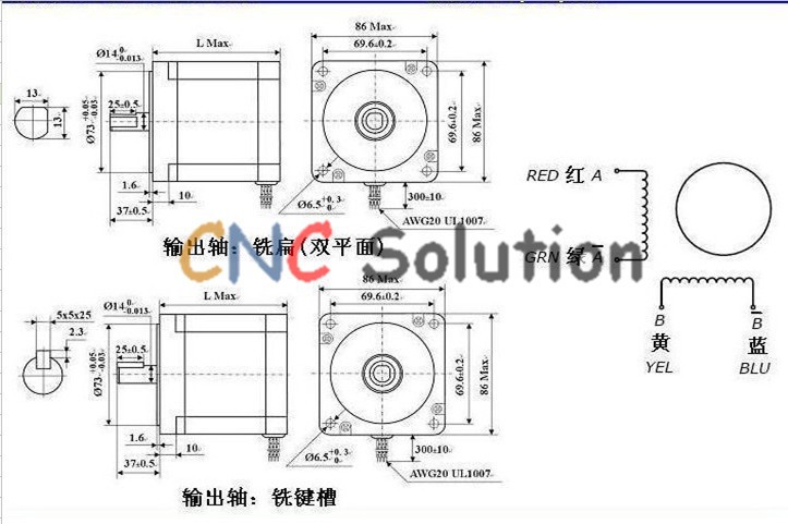


Note: If you need the dual shaft stepper motor, please leave message to us after order , If no message left, we will ship the single shaft .
Package Including:
stepper motor: 86HS9860A4
|
Step Angle (º) |
Rated Current (A) |
Phase Resistance (ohm) |
Phase Inductance (mH) |
Holding Torque (N*m) |
Detent Torque (N*cm) |
Rotor Inertia (g*cm2) |
Motor Length (mm) |
Motor Wire (No.) |
Motor Weight (kg) |
|
1.8 |
6 |
0.33 |
4.5 |
6.5 |
9.5 |
1.55 |
98 |
4 |
3 |

Stepper driver: MA860H
Electrical Properties (ambient temperature Tj = 25C pm):
|
Parameters |
MA860H |
|||
|
Min. |
Typical |
Max. |
Unit |
|
|
Output Current |
2.6 |
- |
7.8(5.6RMS) |
A |
|
Supply Voltage |
18 |
60 |
80 |
VAC |
|
+24 |
+80 |
+110 |
VDC |
|
|
Logic Signal Current |
7 |
10 |
16 |
mA |
|
Pulse Input Frequency |
0 |
- |
300 |
kHz |
|
Isolation Resistance |
500 |
- |
- |
Mohm |
Connector P1 Configurations:
|
PIN |
Details |
|
PUL+ |
Pulse signal: In single pulse (pulse/direction) mode, this input represents pulse signal; 4-5V when PUL-HIGH, 0-0.5V when PUL-LOW. In double pulse mode(pulse/pulse) , this input represents clockwise (CW) pulse,active at high level or low level (set by inside jumper J1 & J2). For reliable response, pulse width should be longer than 1.5μs. Series connect resistors for current-limiting when+12V or +24V used. The same as DIR and ENA signals. |
|
DIR+ |
DIR signal: In single-pulse mode, this signal has low/high voltage levels,representing two directions of motor rotation; in double-pulse mode (set by inside jumper J1 & J2), this signal is counter-clock (CCW) puls. For reliable motion response, DIR signal should be ahead of PUL signal by 5μs at least. 4-5V when DIR-HIGH,0-0.5V when DIR-LOW. Please note that motion direction is also related tomotor-driver wiring match. Exchanging the connection of ?two wires for a coilto the driver will reverse motion direction. |
|
ENA+ |
Enable signal: This signal is used for enabling/disabling the driver. High level(NPN control signal, PNP and Differential control signals are on the contrary,namely Low level for enabling.) for enabling the driver and low level fordisabling the driver. Usually left UNCONNECTED (ENABLED) |
Connector P2 Configurations:
|
PIN |
Details |
|
+V |
Power supply, 18~80 VDC or 24~110VDC, Including voltage fluctuation and EMF voltage. |
|
GND |
Power Ground |
|
A+, A- |
Motor Phase A |
|
B+, B- |
Motor Phase B |
Power supply: S-400-60
Model: S-400-60
Product Specifications
Input voltage: AC110-230V (supports 110V has a pull switch)
Output voltage: DC60V 6.7A
Output Power: 400W
Size: 215 * 115 * 50MM
Weight: 1.15KG
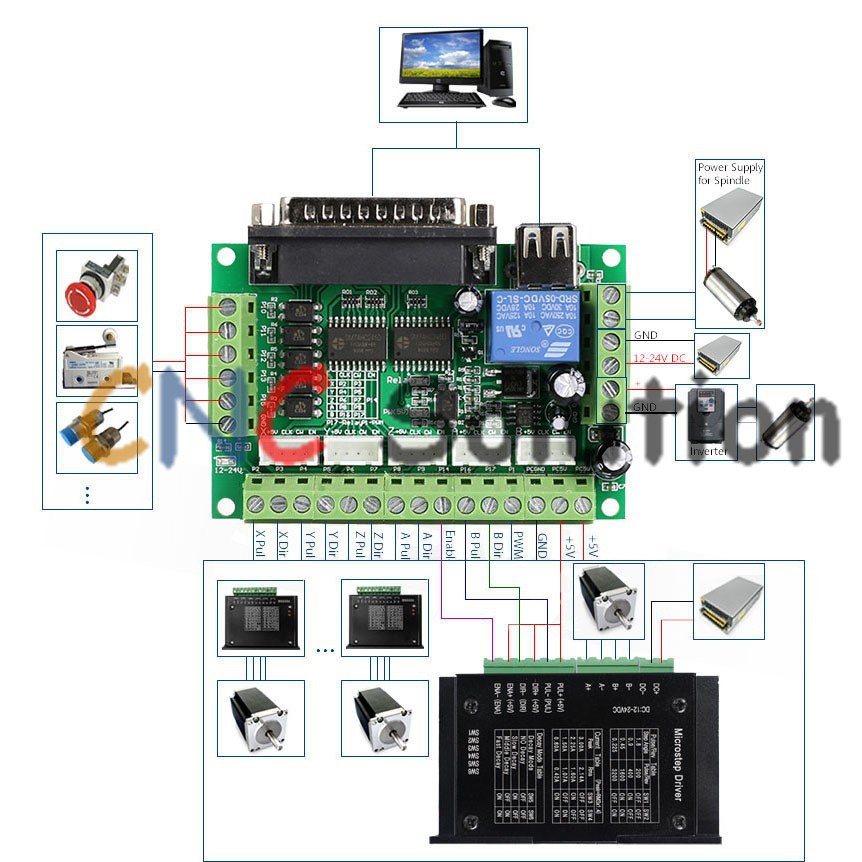
5 axis CNC Breakout Board:

Electrical properties (ambient temperature Tj = 25C pm):
|
Input Voltage |
USB port from PC or 12-24V power supply(optional) |
|
Drive type |
Pulse and Direction Signal Control |
|
Suitable Microstep Driver |
2 Phase Microstep Driver |
|
Net weight |
Approx 75g |
|
Dimensions |
90 * 70 * 20mm (L*W*H) |
Tell us what you think about this item, share your opinion with other people. Please make sure that your review focus on this item. All the reviews are moderated and will be reviewed within two business days. Inappropriate reviews will not be posted.
Have any question or inquire for this item? Please contact us. Our customer representative will get back shortly.